Enquire Now >

Thermographic Cold Storage and Separation Inspections

We have successfully used thermographic testing to monitor cold stores. Using infrared it is easy to see where a heated door seal is failing, or where a leak has occurred within the cold store itself. Where there are such extremes of temperature in this environment, the anomalies show up extremely well and can guide engineers to the exact point of the problem.

Incontinuity in insulation also proves a problem in cold stores, meaning more energy is used to keep a constant temperature, as the images show.

Cold Storage thermal Inspection

Identify and locate the problem

Cold Storage thermal Inspection

Cold Store Insulation Surveys

Cold Storage thermal Inspection

Locate insulation breakdown

Reduce Risks

Reduce costs by eliminating risk before it becomes a problem

Early Detection

Detect fire hazards early on and save money

Non-Destructive

Non-destructive testing which allows for in-depth inspections without causing damage

Zero Downtime

Get fully inspected without needing to stop operations

MEASUREMENT – VESSEL INTERNAL LEVELS

The use of thermal imaging cameras on process equipment such as vessels, separators and tanks can span numerous applications from internal fluid or sediment levels to insulation integrity and other structural issues.

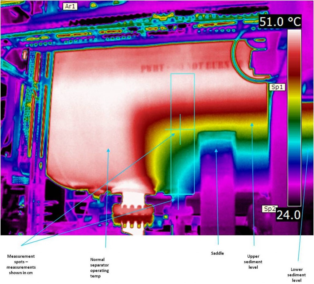
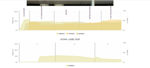
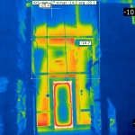
Our purpose-built TICOR™ measurement module can not only indicate where sediment levels lie within a vessel or separator but accurately measure them and offer a cm and % level which is fully trendable between inspections. This will offer you the ability to accurately assess sediment deposits during the initial inspection then to monitor changes during subsequent periodic inspections.

The TICOR™ measurement module is an exceptionally efficient and fast method of providing detailed thermograms of this type of equipment and it provides comparative graphs for each periodic inspection.

Using TICOR Measurement Module

You take a very important detailed scan then analyse the images using the measurement tools within the module. It requires the sections to be identified within the item by adding four lines on the image, the left and right lines, the bottom to identify the base and then the top line to indicate where on the separator or vessel we are inspection. This top line is critical and we must indicate its overall height against the separator or vessel so that the graph can be accurately drawn. We then add the points where we believe the level to be. There are no limits to measurement points providing the ability to follow where the line appears to be on the thermogram.